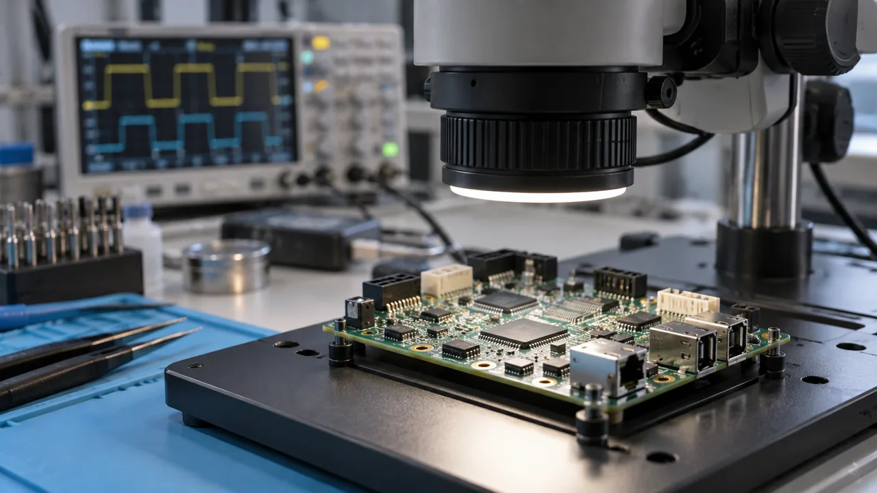
A Raspberry Pi 5 with a camera module is one prototyping option when cycle time, interfaces, environmental conditions and maintenance requirements fit. Field issues may come from software as well as 5V rail sag, USB-C PD mismatch, heat in a metal enclosure or vibration shifting focus.
Power budget
Calculate startup and continuous current for the camera, SSD, HAT and other peripherals from manufacturer data and measurements; allow suitable headroom for temperature, cable loss and transient loads. Use a supply with a manufacturer-approved voltage/current profile and a low-loss cable, then verify voltage under load.
Vibration
Do not mount the camera directly to the machine frame without measuring the vibration spectrum and image blur at that point. Test options such as elastomer feet or a separate stand against resonance, field of view and maintenance access; retain control images that distinguish focus shift from model error.
Enclosure, power, thermal management and mechanical mounting should be acceptance-tested alongside model performance. Verify image quality, cycle time and failure behaviour in the same field scenario before and after the software demonstration.