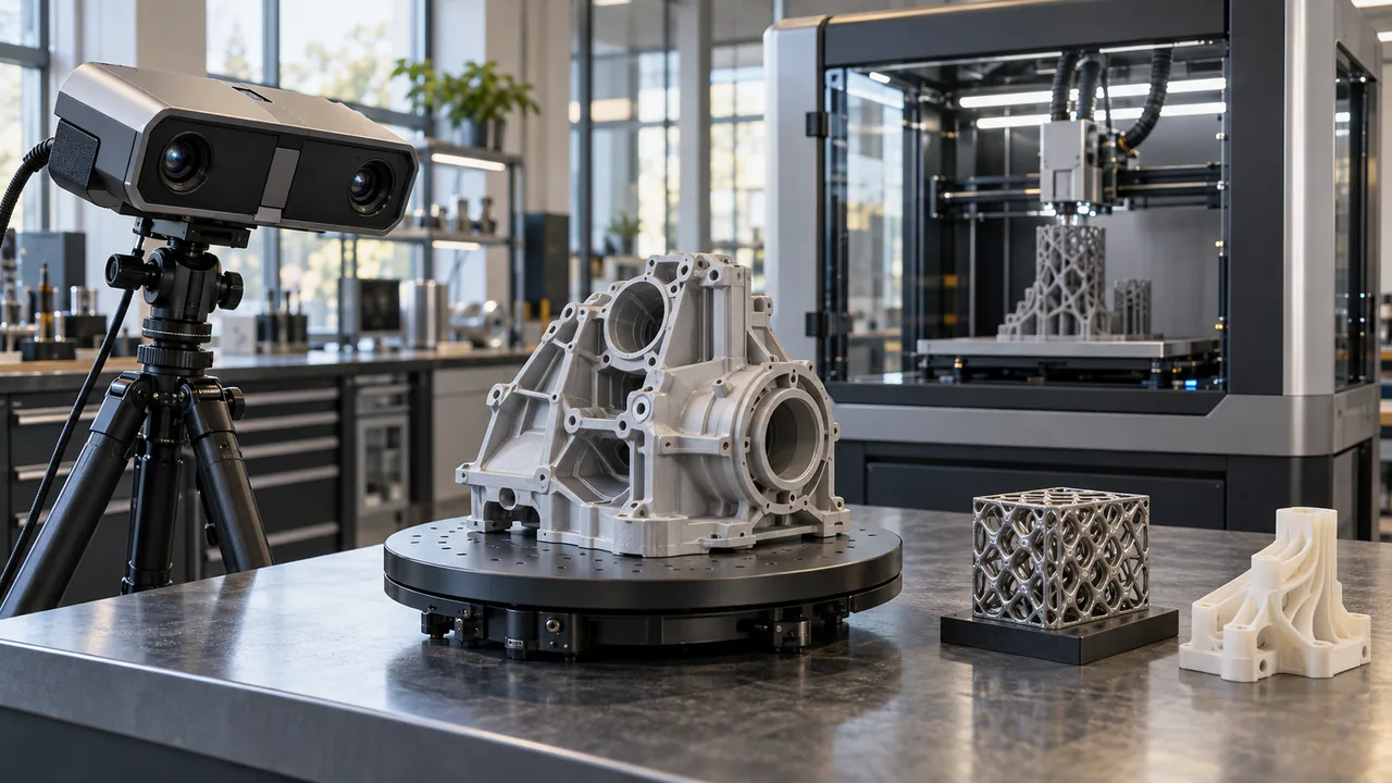
Digitising an existing part is different from obtaining a production-ready design. 3D scanning captures surface data; reverse engineering translates that data into dimensions, geometric relationships and design intent. A 3D printer then turns the selected model and material into a physical part using a particular manufacturing process. Define deliverables and acceptance criteria for each step separately.
Match scanning scope to the part
Part size, reflective surfaces, dark or transparent areas and inaccessible internal geometry affect the scanning method. Reference markers, alignment and surface preparation should be included in the scope. A scanner’s published accuracy does not mean that every part will be delivered to that accuracy; assess the result together with the measurement conditions and validation method.
Distinguish mesh data from CAD geometry
Mesh formats such as STL or OBJ may suffice for visualisation and some printing tasks. Editable parametric models, technical drawings or manufacturing data require additional modelling. Reconstructing nominal geometry instead of copying a worn part is a separate engineering decision. Agree file formats, revisions and intellectual-property scope before ordering.
Validate prototypes against their intended use
Visual models, assembly trials and functional parts need different materials and printing strategies. Loads, temperatures, chemical exposure, surface finish and dimensional requirements affect material selection and build orientation. The proposal should state whether post-processing and dimensional inspection are included. Suitability for critical end uses requires separate validation.
- Scanning and data processing
- CAD modelling and design revisions
- Materials, printing time and post-processing
- Dimensional inspection, technical files and delivery terms