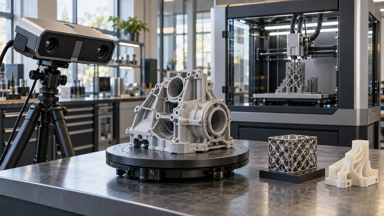
The first question in a visual inspection project is not camera resolution. Define which defect must be distinguished, at what size and under which production conditions. Scratches, missing parts, assembly errors, label defects and dimensional deviations may require different imaging setups. Good and defective samples help ensure that acceptance criteria represent real production.
The optical setup determines the result
Select the field of view, working distance, lens, exposure and lighting together. Software alone cannot compensate for uncontrolled reflections on shiny metal, low contrast on dark surfaces or motion blur. Thermal imaging additionally requires attention to emissivity, reflected temperature, distance and environmental conditions. A camera image does not automatically constitute a calibrated temperature or dimensional measurement.
Distinguish measurement from classification
A model classifying a part as acceptable or defective does not by itself prove that the measurement system meets the required tolerance. Reference measurements, repeatability and false acceptance/rejection rates need separate assessment. Test data should cover different shifts, batches and surface conditions. Testing with the same images used for training can overstate actual performance.
Link inspection results to production records
Camera triggering, PLC communications, cycle time and rejection mechanisms belong to the same control sequence. Define system behaviour when communications fail or an image cannot be acquired. Recording the result with a serial number, timestamp, station and inspection version enables the quality team to investigate nonconformances later.
What should the proposal itemise?
- Cameras, lenses, lighting, mounts and protective equipment
- Software, licences, model development and data preparation
- PLC/ERP/MES integration and site commissioning
- Sample set, acceptance testing, training and maintenance scope