Opsan is an industrial manufacturer in automotive sheet-metal production. This project covers rework on the engine subframe for the Ford Courier family, produced by Ford Otosan at its Craiova plant in Romania. AIOR Vision is a process-traceability and reporting system developed for Opsan. Weld-quality measurement and automatic acceptance or rejection decisions are outside its scope.
INDUSTRIAL AUTOMATION · TRACEABILITY
Opsan
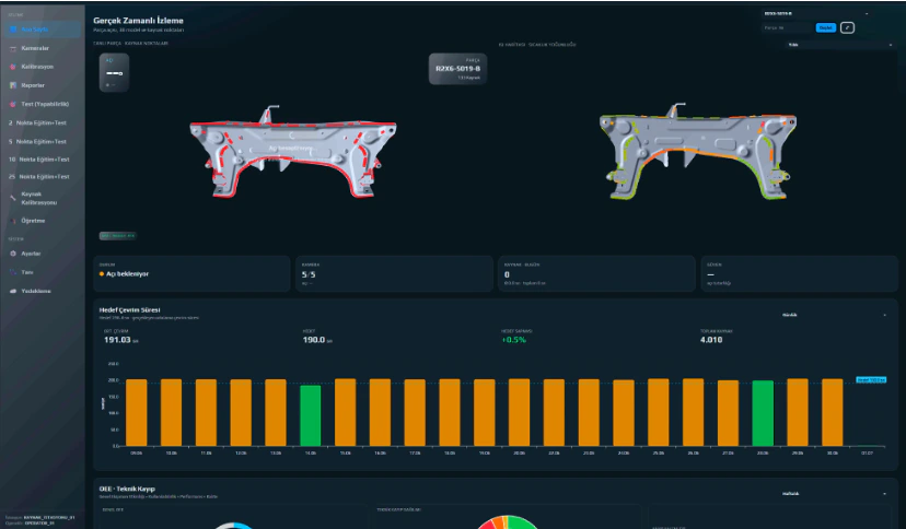
AIOR Vision for Opsan is our flagship industrial project. At the Ford Courier engine-subframe rework station, we bring five camera views together with a 3D part map of approximately 130 zones to turn welding activity into traceable production records. Each event carries its part identity, working plane, weld zone and timestamp. The operator HMI, heatmaps, detailed queries and cloud reports share the same engineering foundation. Validated through demonstration and real-part setups, the solution is moving into site implementation following customer acceptance and order approval.
PROJECT GALLERY
Screens from the delivered digital experience
PROJECT STORY
Project overview and scope
AIOR Vision for Opsan is our flagship industrial project. At the Ford Courier engine-subframe rework station, we bring five camera views together with a 3D part map of approximately 130 zones to turn welding activity into traceable production records. Each event carries its part identity, working plane, weld zone and timestamp. The operator HMI, heatmaps, detailed queries and cloud reports share the same engineering foundation. Validated through demonstration and real-part setups, the solution is moving into site implementation following customer acceptance and order approval.
We designed the data flow from barcode identification through to management reporting. Five-camera imaging, positioner-angle data and the 3D zone map meet within a shared part session. The local record layer retains event duration, detection confidence, camera health and synchronisation state. The HMI shows the active part and working surface; the web panel provides part- and weld-point queries, heatmaps, role-based access, seven standard reporting ranges and CSV exports.
Approximately 130 weld zones are distributed across different surfaces and working planes. Visibility changes as the positioner rotates, and the operator, torch and fixture can partially obscure a view. The engineering challenge was to associate visible welding activity with the correct part and 3D zone. The same record chain also needed to give operators a clear interface, production teams a queryable history and the station a local capture path during network interruptions.
We built the approach around the 3D part model, fixture geometry and positioner movement. Weld zones were mapped by plane, and the five camera views were planned around that map. Location, event and time data were linked to each barcode-opened part session. The operator HMI prioritises the active part, working surface and system state; detailed analysis is brought together in the web panel. Heatmaps show where activity occurs across the part, while reports from hourly to yearly reveal differences between periods. While local devices remain healthy and storage capacity is available, records are buffered during connectivity loss and transferred to the redundant two-server cloud layer when the connection returns.
DELIVERABLES
Modules completed within the project
- 01Five-camera vision design around part geometry and working angles
- 023D mapping and site calibration for approximately 130 weld zones
- 03Matching barcode, positioner angle, welding event and time within one session
- 04Operator HMI, rotatable 3D part view and heatmaps
- 05Role-based web panel, detailed queries, period reports and CSV exports
- 06Local buffering and redundant two-server cloud synchronisation
TECHNOLOGY STACK
Platforms and tools used
AIOR Vision5-Camera Vision3D Zone MappingIndustrial HMIHeatmap AnalyticsOffline-first EdgeRedundant Cloud SyncRole-based Reporting
≈130
Weld/rework zones defined on the 3D map
5
Optimised camera views
2
Servers in the redundant cloud layer
7
Standard reporting time ranges
AIOR PROJECT NOTE
Opsan AIOR Vision is our flagship industrial project, bringing computer vision, 3D geometry, industrial interfaces and data engineering together around one production challenge.
Delivered scope and continuity
We validated the solution in two stages. The first setup demonstrated arc-light tracking with a demonstration part and project-specific software. The second used the real Ford Courier engine subframe, fixture and gas-shielded welding process. The customer team reviewed the mapping of camera events to 3D zones, the operator workflow and the reporting infrastructure. A successful acceptance test led to order approval. Adaptation to the Opsan station, site calibration and commissioning remain in progress.